Building a wireless Temperature/Humidity Sensor using the InPlay IN100
✅ Note: No Programming Is Required For This Project!
Introduction
Environmental sensing applications have been around for centuries, from recording temperature, humidity, air pressure, and many more.
But only in the past decade or so have we been able to wirelessly connect many of these sensors in very small physical form factors and cost-effectively.
With the InPlay IN100, you can wirelessly connect almost any type of sensor supporting the most common protocols, including I2C, Single-wire, GPIO, and analog (via the built-in ADC). And this is not limited to just one sensor; you can connect multiple sensors and configure your application to broadcast the data read from all sensors in a single packet or multiple separate packets.
And all this without writing a single line of code!
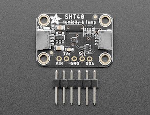
In this project, we will connect the SHT40 sensor from Sensirion. The sensor provides both temperature and humidity readings and utilizes the I2C protocol. You can learn more about the I2C protocol here.
We'll be using the Adafruit breakout board for this sensor (you'll need to solder the header pins to the board):
The project is a great starting point for building your own wireless weather station!
I2C Support on IN100 and in NanoBeacon™ Config Tool
💡 Note: If you're unfamiliar with the InPlay IN100 chipset, I recommend checking out "Getting Started with the InPlay NanoBeacon™ IN100" (15 min) before moving on with this project.
The IN100 supports up to three connected I2C slaves/peripherals, each with its own configuration in the NanoBeacon™ Config Tool application:
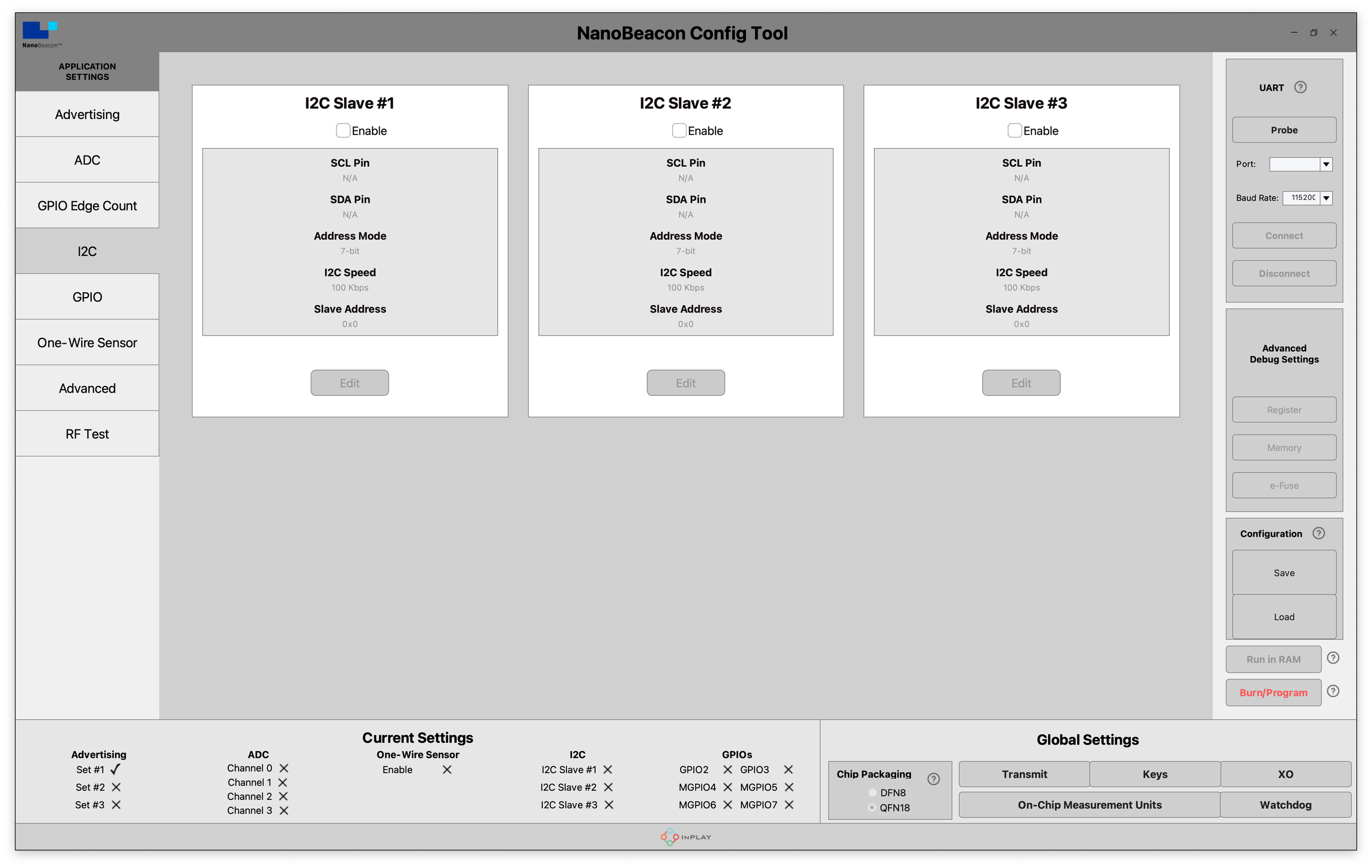
For each I2C slave, we have the following settings (accessed by first enabling the I2C Slave and then clicking Edit):

Let's take a look at each of these settings and configure them for our sensor.
PIN Select
We have different options for which pins we want to connect both the SDA and SCL lines from the sensor.
The available pins are GPIO2, GPIO3, MGPIO4, MGPIO5, and MGPIO7 ("GPIO" refers to digital input pins, and "MGPIO" refers to mixed signal pins supporting both analog and digital inputs). For our application, we'll configure SCL→ GPIO2 and SDA → GPIO3.
Address Mode
This is to configure the address mode used by the I2C slave (7-bit mode is the most common).
For our application, we'll be using the 7-bit address mode.
I2C Speed
We have two options for the data rate used: 100 kbps and 400 kbps.
For our application, we'll be using the 100 kbps speed setting.
Slave Address
Here you will specify the I2C slave address based on the information provided by the manufacturer (on the webpage or in the datasheet).
For our application, the I2C slave address is 0x44.
Read Data Storage Settings
These settings define the buffer that will store the data being read from the I2C sensor. In our case (as you'll see later on when we refer to the spreadsheet), for each reading, we will need to store 6 bytes, so we'll be setting this value to 6.
Notice that the Memory Address and Offset are grayed out and unavailable to be modified by the user.
Finally, we have the I2C Commands section, which is where we can configure what commands the IN100 will send (reading, writing), the sequence of these commands, and when certain commands should happen:

i2c_read → number of bytes to read. There is a maximum of 5 bytes that can be read with a single command. If you need to read more than 5 bytes, then you can include multiple consecutive read commands.
i2c_write → bytes to be written, in hex format, separated by commas. If you need to write more than 5 bytes, then you can include multiple consecutive write commands.
i2c_write_stop_read → a convenience command that allows you to write, stop, and read, all in one go.
delay_command → allows you to insert a command in microseconds.
Below the commands, we have a couple of checkboxes that we can enable for each command:
The "Execute I2C command when cold boot" is used to tag the command to be run during "cold boot" (at power-on of the chip). Typically, this is the initial configuration of the I2C sensor.
The "Execute I2C command when warm boot" is used to tag the command to be run during "warm boot" (after each wakeup from sleep event). These commands will be run at each wakeup event.
If we need a command to be run during both cold boot and warm boot, then we can check both boxes. If the command needs to be run in only one of these conditions, then check the box that corresponds to that.
To add a command, we choose its type, fill out the fields with the necessary values and then click Add.
We can also insert commands in a specific location within the existing commands in the list, and then finally, we can delete commands from the list.
The steps to configure I2C commands are as follows:
Select a command, and enter the details for that command
Select the execution condition (by checking/unchecking the cold boot and/or warm boot boxes)
Click the “add” button to add the command to the configuration.
Repeat the above process, adding another command as needed
SHT40 I2C Configuration
When working with an I2C sensor, it is crucial to refer to its datasheet to understand exactly what you need to do to configure the sensor and be able to read its data correctly.
You can download the SHT40 sensor datasheet here.
From the datasheet, we need to find out three pieces of information:


The format of the write commands and the format of the responses from the sensor (that we need to read)
The write command values that are available
Finally, the formula(s) used to interpret the sensor readings and convert them into meaningful values
For the SHT40, here are the relevant pieces of information:
So, essentially, we just need to set up the I2C commands in the following order:
1. We will add a command to write0xFD on both cold boot and warm boot.

2. Next, we will add commands to read 6 bytes. Given the 5-byte limit (mentioned earlier), I chose to add six separate commands of reading one byte each (then removing the inserted null). These are also added for both cold boot and warm boot conditions.
And that's it in terms of I2C configuration!
Advertising Set Configuration
We would like to include the following in our advertising packets:
Device Name: "IN100"
Manufacturer Specific Data: raw sensor reading data
To do this:

Now we have the advertising data configured.
Let's move on to the next step!
Hardware Connections
Let's take a look at the PIN connections between the SHT40 breakout board and the IN100 development board:

The connections are as follows:
VBAT (IN100) → 3Vo (SHT40)
GPIO 3 (IN100) → SDA (SHT40)
GPIO 2 (IN100) → SCL (SHT40)
GND (IN100) → GND (SHT40)
Testing
⚠️ Note: One important thing to note is that when testing I2C functionality on the IN100, we cannot use the "Run in RAM" option that temporarily flashes the configuration to the device.
Instead, we need to use the "Burn/Program" operation, which permanently writes the configuration to the device. So, before you do this, you will need to ensure that the configuration settings are all 100% correct.
Once you double-check all the configuration settings, click the "Burn/Program" button to flash the device.

Interpretation of the Sensor Readings
For an I2C sensor, you will need to refer to the datasheet to understand how to interpret the data it outputs.
For the SHT40, this is what we have:

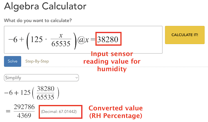
To make this conversion process much easier, I've input the conversion equation into a handy online tool for the temperature and humidity readings.
You can find each of these configured conversions here:

Let's do some testing and see it in action!
I'm using the nRF Connect mobile app for Android to capture the advertising packets broadcast by the IN100. Here's an example of a reading:

Now that we have the sensor data, we can convert each value (temperature and humidity).
Temperature:
We plug the value (27793) into the online converter:

This gives us a temperature reading of 29.22 degrees Celsius.
Humidity:
We plug the value (37843) into the online converter:

This gives us a humidity reading of 66.18% Relative Humidity.
And that's it! That was simple, right?!
Summary
In this article, we learned about:
The InPlay IN100 features relating to I2C sensors
How to build and configure the IN100 to interface with the SHT40 temperature/humidity sensor over I2C
How to configure the IN100 to broadcast the sensor data and capture it using a BLE scanner mobile app
How to interpret the values read from the sensor